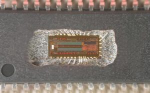
 Break Chip ATMEGA861P Code
Timer 2 is selected as the baud rate generator by setting TCLK and/or RCLK in T2CON (Table 2). Note that the baud rates for transmit and receive can be different if Timer 2 is used for the receiver or transmitter and Timer 1 is used for the other function. Setting RCLK and/or TCLK puts Timer 2 into its baud rate generator mode, as shown in Figure 4 when Break Chip ATMEGA861P Code.
The baud rate generator mode is similar to the auto-reload mode, in that a rollover in TH2 causes the Timer 2 registers to be reloaded with the 16 bit value in registers RCAP2H and RCAP2L, which are preset by Copy IC PIC16LF877 Program.
The baud rates in Modes 1 and 3 are determined by Timer 2’s overflow rate according to the following equation. The Timer can be configured for either timer or counter operation. In most applications, it is configured for timer operation (CP/T2 = 0).
The timer operation is different for Timer 2 when it is used as a baud rate generator. Normally, as a timer, it increments every machine cycle (at 1/12 the oscillator frequency). As a baud rate generator, however, it increments every state time (at 1/2 the oscillator fre-quency) to facilitate the progress of Attack Chip ST62T00CB6 Firmware.
The baud rate formula is given below. where (RCAP2H, RCAP2L) is the content of RCAP2H and RCAP2L taken as a 16 bit unsigned integer.
This figure is valid only if RCLK or TCLK = 1 in T2CON. Note that a rollover in TH2 does not set TF2 and will not generate an interrupt. Note too, that if EXEN2 is set, a 1-to-0 transition in T2EX will set EXF2 but will not cause a reload from (RCAP2H, RCAP2L) to (TH2, TL2) to better support the progress of Attack Microcontroller MC68HC705P6ACDW Binary.
Thus when Timer 2 is in use as a baud rate generator, T2EX can be used as an extra external interrupt. Note that when Timer 2 is running (TR2 = 1) as a timer in the baud rate generator mode, TH2 or TL2 should not be read from or written to Attack MCU TMX320F28027PTA Archive.
Under these conditions, the Timer is incremented every state time, and the results of a read or write may not be accurate. The RCAP2 registers may be read but should not be written to, because a write might overlap a reload and cause write and/or reload errors. The timer should be turned off (clear TR2) before accessing the Timer 2 or RCAP2 registers after Unlock Microcontroller Memory.
