Archive for April, 2015
 Break IC PIC12C508A Flash
A variety of packaging options are available which the engineer should pay attention when Break IC PIC12C508A Flash. Depending on application and production requirements, the proper device option can be selected using the information in this section. When placing orders, please use the PIC12C5XX Product Identification System at the back of this data sheet to specify the correct part number.
The UV erasable version, offered in ceramic side brazed package, is optimal for prototype development and pilot programs.
Break IC PIC12C508A Flash
The UV erasable version can be erased and reprogrammed to any of the configuration modes.
Microchip’s PICSTART® PLUS and PRO MATE® programmers all support programming of the PIC12C5XX.
Third party programmers also are available; refer to the Microchip Third Party Guide for a list of sources. The availability of OTP devices is especially useful for customers who need the flexibility for frequent code updates or small volume applications, if not, we can see Recover Microcontroller TMS320F2812PGFA Firmware as a feasible solution for it.
The OTP devices, packaged in plastic packages permit the user to program them once. In addition to the program memory, the configuration bits must also be programmed.
Microchip offers a QTP Programming Service for factory production orders. This service is made available for users who choose not to program a medium to high quantity of units and whose code patterns have stabilized.
The devices are identical to the OTP devices but with all EPROM locations and fuse options albreaky programmed by the factory after Crack MCU. Certain code and prototype verification procedures do apply before production shipments are available. Please contact your local Microchip Technology sales office for more details.
Microchip offers a unique programming service where a few user-defined locations in each device are programmed with different serial numbers. The serial numbers may be random, pseudo-random or sequential. Serial programming allows each device to have a unique number which can serve as an entry-code, password or ID number in the process of Break MCU AT89C5131A Binary. Microchip offers masked ROM to give the customer a low cost option for high volume, mature products.
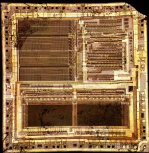
Reverse Engineering Microcontroller PIC16C558A Eeprom
The clock input (OSC1/CLKIN pin) is internally divided by four to generate four non-overlapping quadrature clocks namely Q1, Q2, Q3 and Q4. Internally, the program counter (PC) is incremented every Q1 if Reverse Engineering Microcontroller PIC16C558A Eeprom, the instruction is fetched from the program memory and latched into the instruction register in Q4. The instruction is decoded and executed during the following Q1 through Q4..
An “Instruction Cycle” consists of four Q cycles (Q1, Q2, Q3 and Q4). The instruction fetch and execute are pipelined such that fetch takes one instruction cycle while decode and execute takes another instruction cycle similar to the process of Reverse Engineering Microcontroller PIC16F73 Program.
Reverse Engineering Microcontroller PIC16C558A Eeprom
However, due to the pipelining, each instruction effectively executes in one cycle. If an instruction causes the program counter to change (e.g., GOTO) then two cycles are required to complete the instruction (Example 3-1) after Reverse engineering Microcontroller. A fetch cycle begins with the program counter (PC) incrementing in Q1.
In the execution cycle, the fetched instruction is latched into the “Instruction Register (IR)” in cycle Q1. This instruction is then decoded and executed during the Q2, Q3, and Q4 cycles. Data memory is read during Q2 (operand read) and written during Q4 (destination write).
The PIC16C55X(A) has a 13-bit program counter capable of addressing an 8K x 14 program memory space. Only the first 512 x 14 (0000h – 01FFh) for the PIC16C554(A), 1K x 14 (0000h – 03FFh) for the PIC16C556A and 2K x 14 (0000h – 07FFh) for the PIC16C558(A) are physically implemented.
Accessing a location above these boundaries will cause a wrap-around within the first 512 x 14 space PIC16C554(A) or 1K x 14 space PIC16C556A or 2K x 14 space PIC16C558(A). The reset vector is at 0000h and the interrupt vector is at 0004h when Recover MCU PIC16F74A Binary.
The data memory (Figure 4-4 and Figure 4-5) is partitioned into two Banks which contain the general purpose registers and the special function registers. Bank 0 is selected when the RP0 bit is cleared. Bank 1 is selected when the RP0 bit (STATUS <5>) is set.
The Special Function Registers are located in the first 32 locations of each Bank. Register locations 20-6Fh (Bank0) on the PIC16C554(A)/556A and 20-7Fh (Bank0) and A0-BFh (Bank1) on the PIC16C558(A) are general purpose registers implemented as static RAM when Reverse Engineering Microcontroller PIC16C558A Eeprom. Some special purpose registers are mapped in Bank 1