Posts Tagged ‘reverse engineering IC protected flash’
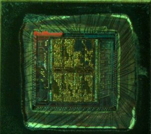
 Reverse Engineering IC PIC18F248 Binary
Reverse Engineering IC PIC18F248 and locate the fuse bit position, crack mcu pic18f248 flash memory by focus ion beam and copy the embedded firmware from microcontroller pic18f248;

High-Performance RISC CPU:
· Linear program memory addressing up to 2 Mbytes
· Linear data memory addressing to 4 Kbytes
· Up to 10 MIPS operation
· DC – 40 MHz clock input
· 4 MHz-10 MHz oscillator/clock input with PLL active when copy microcontroller pic16f737 flash memory
· 16-bit wide instructions, 8-bit wide data path
· Priority levels for interrupts
· 8 x 8 Single-Cycle Hardware Multiplier
Peripheral Features:
· High current sink/source 25 mA/25 mA
· Three external interrupt pins
· Timer0 module: 8-bit/16-bit timer/counter with 8-bit programmable prescaler
· Timer1 module: 16-bit timer/counter
· Timer2 module: 8-bit timer/counter with 8-bit period register (time base for PWM)
· Timer3 module: 16-bit timer/counter
· Secondary oscillator clock option – Timer1/Timer3
· Capture/Compare/PWM (CCP) modules; CCP pins can be configured as:
– Capture input: 16-bit, max resolution 6.25 ns
– Compare: 16-bit, max resolution 100 ns (TCY) before break mcu pic18f442 software
– PWM output: PWM resolution is 1 to 10-bit Max. PWM freq. @:8-bit resolution = 156 kHz 10-bit resolution = 39 kHz
· Enhanced CCP module which has all the features of the standard CCP module, but also has the following features for advanced motor control:
– 1, 2 or 4 PWM outputs
– Selectable PWM polarity
– Programmable PWM dead time
· Master Synchronous Serial Port (MSSP) with two modes of operation:
– 3-wire SPI™ (Supports all 4 SPI modes) after Reverse engineering IC
– I2C™ Master and Slave mode
· Addressable USART module:
– Supports interrupt-on-address bit
Advanced Analog Features:
· 10-bit, up to 8-channel Analog-to-Digital Converter module (A/D) with:
– Conversion available during Sleep
– Up to 8 channels available
· Analog Comparator module:
– Programmable input and output multiplexing
· Comparator Voltage Reference module
· Programmable Low-Voltage Detection (LVD) module:
– Supports interrupt-on-Low-Voltage Detection
· Programmable Brown-out Reset (BOR)
CAN bus Module Features:
· Complies with ISO CAN Conformance Test
· Message bit rates up to 1 Mbps
· Conforms to CAN 2.0B Active Spec with:
– 29-bit Identifier Fields
– 8-byte message length
– 3 Transmit Message Buffers with prioritization
– 2 Receive Message Buffers
– 6 full, 29-bit Acceptance Filters
– Prioritization of Acceptance Filters
– Multiple Receive Buffers for High Priority Messages to prevent loss due to overflow
– Advanced Error Management Features
Special Microcontroller Features:
· Power-on Reset (POR), Power-up Timer (PWRT) and Oscillator Start-up Timer (OST)
· Watchdog Timer (WDT) with its own on-chip RC oscillator
· Programmable code protection
· Power-saving Sleep mode
· Selectable oscillator options, including:
– 4x Phase Lock Loop (PLL) of primary oscillator
– Secondary Oscillator (32 kHz) clock input
· In-Circuit Serial ProgrammingTM (ICSPTM) via two pins IC Flash Technology:
· Low-power, high-speed Enhanced Flash technology
· Fully static design Wide operating voltage range (2.0V to 5.5V) Industrial and Extended temperature ranges