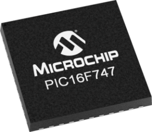
 Reverse Engineering Microcontroller PIC16F747 Code
We can Reverse engineering Microcontroller PIC16F747 Code, please view the Microcontroller PIC16F747 features for your reference:
Special Microcontroller Features:
· Fail-Safe Clock Monitor for protecting critical applications against crystal failure when Reverse engineering Microcontroller code;
· Two-Speed Start-up mode for immediate code execution
· Power-on Reset (POR), Power-up Timer (PWRT) and Oscillator Start-up Timer (OST)
· Programmable Code Protection can be used also for Break Microcontroller PIC18F4220 Binary
· Processor Read Access to Program Memory
· Power-Saving Sleep mode
· In-Circuit Serial Programming (ICSP) via two pins
· MPLAB® In-Circuit Debug (ICD) via two pins
· MCLR pin function replaceable with input only pin
DEVICE OVERVIEW
This document contains device specific information about the following devices:
PIC16F737/767 devices are available only in 28-pin packages, while PIC16F747 devices are available in 40-pin and 44-pin packages. All devices in the PIC16F7X7 family share common architecture with the following differences:
· The PIC16F737 and PIC16F767 have one-half of the total on-chip memory of the PIC16F747 and PIC16F777.
· The 28-pin devices have 3 I/O ports, while the 40/44-pin devices have 5.
· The 28-pin devices have 16 interrupts, while the 40/44-pin devices have 17.
· The 28-pin devices have 11 A/D input channels, while the 40/44-pin devices have 14.
· The Parallel Slave Port is implemented only on the 40/44-pin devices.
· Low-Power modes: RC_RUN allows the core and peripherals to be clocked from the INTRC, while SEC_RUN allows the core and peripherals to be clocked from the low-power Timer1. Refer to Section 4.7 “Power-Managed Modes” for further details for the purpose of Reverse engineering Microcontroller code.
· Internal RC oscillator with eight selectable frequencies, including 31.25 kHz, 125 kHz, 250 kHz, 500 kHz, 1 MHz, 2 MHz, 4 MHz and 8 MHz. The INTRC can be configured as a primary or secondary clock source when Crack MCU. Refer to Section 4.5 “Internal Oscillator Block” for further details.
