 Recovery Chip PIC16F506 Firmware
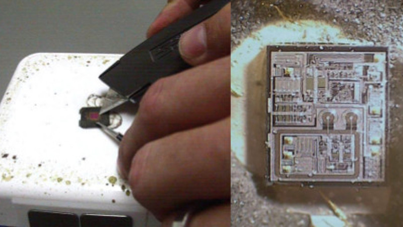
Recovery Chip PIC16F506 Firmware from microcontroller memory, crack PIC16F506 MCU flash and eeprom to readout PIC16F506 MCU code;
Random recovery operations allow the master to access any memory location in a random manner. To perform this type of recovery operation, first the word address must be set. This is done by sending the word address to the device as part of a write operation.
What sets a microcontroller apart from other processors are special circuits to deal with the needs of real-time applications. The PIC16F506 family of microcontrollers has a host of such features intended to maximize system reliability, minimize cost through elimination of external components, provide power saving operating modes and offer code protection when Reverse engineering Chip pic18f248 binary firmware.
These features are:
Oscillator selection
Reset
– Power-On Reset (POR)
– Device Reset Timer (DRT)
– Wake-up from SLEEP on pin change
Watchdog Timer (WDT)
SLEEP
Code protection
ID locations
In-circuit Serial Programming
The PIC16F506 has a Watchdog Timer which can be shut off only through configuration bit WDTE. It runs off of its own RC oscillator for added reliability.
If using XT or LP selectable oscillator options, there is always an 18 ms (nominal) delay provided by the Device Reset Timer (DRT), intended to keep the chip in reset until the crystal oscillator is stable.
If using INTRC or EXTRC there is an 18 ms delay only on VDD power-up. With this timer on-chip, most applications need no external reset circuitry.
The SLEEP mode is designed to offer a very low current power-down mode. The user can wake-up from SLEEP through a change on input pins or through a Watchdog Timer time-out. Several oscillator options are also made available to allow the part to fit the application, including an internal 4 MHz oscillator. The EXTRC oscillator option saves system cost while the LP crystal option saves power.
A set of configuration bits are used to select various options. The PIC16F506 configuration word consists of 12 bits. Configuration bits can be programmed to select various device configurations. Two bits are for the selection of the oscillator type, one bit is the Watchdog Timer enable bit, and one bit is the MCLR enable bit.