 Attack MCU MSP430G2452IPW14R Heximal
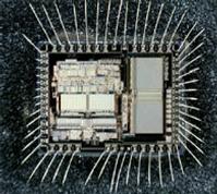
Attack MCU MSP430G2452IPW14R flash memory and extract heximal from Microcontroller MSP430G2452, the status of Microprocessor will be reset from locked to open one after get access to the databus
Attack MCU MSP430G2452IPW14R flash memory and extract heximal from Microcontroller MSP430G2452, the status of Microprocessor will be reset from locked to open one after get access to the databus;
FEATURES
Low Supply Voltage Range: 1.8 V to 3.6 V
Ultra-Low Power Consumption
– Active Mode: 220 µA at 1 MHz, 2.2 V
– Standby Mode: 0.5 µA
– Off Mode (RAM Retention): 0.1 µA
Five Power-Saving Modes
Ultra-Fast Wake-Up From Standby Mode in Less Than 1 µs
16-Bit RISC Architecture, 62.5-ns Instruction Cycle Time Basic Clock Module Configurations
– Internal Frequencies up to 16 MHz With
Four Calibrated Frequencies
– Internal Very-Low-Power Low-Frequency (LF) Oscillator
– 32-kHz Crystal
– External Digital Clock Source
One 16-Bit Timer_A With Three Capture/Compare Registers
Up to 16 Touch-Sense Enabled I/O Pins
Universal Serial Interface (USI) Supporting SPI and I2C
10-Bit 200-ksps Analog-to-Digital (A/D)
Converter With Internal Reference, Sample-and-Hold, and Autoscan (MSP430G2x52 Only)
On-Chip Comparator for Analog
Brownout Detector Serial Onboard Programming,
No External Programming Voltage Needed,
Programmable Code Protection by Security Fuse
On-Chip Emulation Logic With Spy-Bi-Wire Interface
Family Members are Summarized in Table 1 Package Options
– TSSOP: 14 Pin, 20 Pin
– PDIP: 20 Pin
– QFN: 16 Pin
For Complete Module Descriptions, See the MSP430x2xx Family User’s Guide (SLAU144)